
Do you have individual column sections and angled wall geometries, and need punching shear design for them?
No problem. In RFEM 6, you can perform punching shear design not only for rectangular and circular sections, but for any cross-section shape.

In the Construction Stages Analysis (CSA) add-on, you can use built-up cross-sections by means of what are known as phase sections. This allows you to activate and deactivate the parts of the "Parametric - Massive II" section type throughout the construction stages.

The seismic design result is categorized into two sections: member requirements and connection requirements.
The "Seismic Requirements" include the Required Flexural Strength and the Required Shear Strength of the beam-to-column connection for moment frames. They are listed in the ‘Moment Frame Connection by Member’ tab. For braced frames, the Required Connection Tensile Strength and the Required Connection Compressive Strength of the brace are listed in the ‘Brace Connection by Member’ tab.
The program provides the performed design checks in tables. The design check details clearly display the formulas and references to the standard.

You can open the cross-sections in RSECTION using a direct connection, modify them there, and transfer them back to RFEM/RSTAB. Both RSECTION cross-sections and library cross-sections, with the exception of elliptical, semi-elliptical and virtual joists, can be opened and modified directly in RSECTION by clicking a button.
For example, you can thus adjust the reinforcement layout of user-defined RSECTION cross-sections directly in a local RSECTION environment in RFEM/RSTAB. This feature is currently only available for cross-sections with a uniform distribution type. The shear and longitudinal reinforcement defined for library cross-sections is not imported into RSECTION.

The Concrete Design add-on provides you with the option to perform the simplified fire resistance design according to EN 1992‑1‑2 for columns (Section 5.3.2) and beams (Section 5.6).
The following design checks are available for the simplified fire resistance design:
- Columns: Minimum cross-sectional dimensions for rectangular and circular sections according to Table 5.2a as well as Equation 5.7 for calculating time of fire exposure
- Beams: Minimum dimensions and center distances according to Table 5.5 and Table 5.6
You can determine the internal forces for the fire resistance design according to two methods.
- 1 Here, the internal forces of the accidental design situation are included directly into the design.
- 2 The internal forces of the design at normal temperature are reduced by the factor Eta,fi (ηfi), then used in the fire resistance design.
Furthermore, it is possible to modify the axis distance according to Eq. 5.5.

Within the "Plastic capacity design | Simplex Method" in RSECTION, the simultaneous variation of shear stresses over the cross-sectional area is performed in addition to the variation of axial stresses. This extended form of analysis allows you to use redistribution reserves, especially for the cross-sections subjected to shear loading, thus loading the cross-sections even more efficiently.
Go to Explanatory Video
In the design add-ons (such as Steel Design, Timber Design, and so on), you can optimize cross-sections.
The optimization can be performed, for example, for standard cross-sections of a series, or for the width, height, and so on, in the case of parametric cross-sections.
Go to Explanatory Video
The Steel Joints add-on provides you with the option to connect circular hollow sections using welds.
It is possible to connect the circular sections to each other or to planar structural components. The fillets of standard and thin-walled sections can also be connected with a weld.
Go to Explanatory Video
In the Steel Design add-on, you can apply a value for cold-formed sections according to EN 1993‑1‑3, which performs the stability analysis and cross-section design according to Sections 6.1.2 - 6.1.5 and 6.1.8 - 6.1.10.
Go to Explanatory Video
In the Concrete Design add-on, you can design any RSECTION cross-section. Define the concrete cover, shear force, and longitudinal reinforcement directly in RSECTION.
After importing the reinforced RSECTION cross-section into RFEM 6 or RSTAB 9, you can use it for design in the Concrete Design add-on.
Go to Explanatory Video
The "Member Editor" component allows you to modify the individual or several member plates in the Steel Joints add-on.
You can use the chamfer, notch, rounding, and hole operations with multiple shapes. It is possible to apply both operations, "Notch" and "Chamfer", for several member plates.
In this way, you can notch flanges from I-sections, for example (see the image).
Go to Explanatory Video
The design of cold-formed steel members according to the AISI S100-16 / CSA S136-16 is available in RFEM 6. Design can be accessed by selecting “AISC 360” or “CSA S16” as the standard in the Steel Design Add-on. “AISI S100” or “CSA S136” is then automatically selected for the cold-formed design.
RFEM applies the Direct Strength Method (DSM) to calculate the elastic buckling load of the member. The Direct Strength Method offers two types of solutions, numerical (Finite Strip Method) and analytical (Specification). The FSM signature curve and buckling shapes can be viewed under Sections.

In the Steel Joint add-on, you can design the connections of members with composite cross-sections. Furthermore, you can perform joint design checks for almost all thin-walled cross-sections in the RFEM library.
Go to Explanatory Video
You can graphically evaluate result sections for the timber surface design. This can be done in the RFEM graphic as well as in the result history window. The sections can be placed at any location in order to evaluate the design results in detail.

The new steel sections according to the latest CISC Handbook (12th edition) are available in RFEM 6. The sections are listed in the Standardized library. In the filter, select “Canada” for the region and “CISC 12” for the standard. Alternatively, the section name can be directly entered in the search box located at the bottom of the dialog box.

Curved elements are available only in RFEM. It's possible to intersect curved surfaces and solids.
When doing this, the program generates surfaces with the "Trimmed" surface type. With this technology, you can create very complex geometries, such as pipe intersections or curved openings, with a single click.
The intersection of solids is carried out adaptively using the new solid types "Hole" and "Intersection", according to the set theory. Use this method to create new, complex solid geometries similar to the manufacturing process (drilling, milling, turning, etc.). Therefore, it is possible to create complex curved surface or perforated solid elements. It's a simple process!
Go to Explanatory Video
Would you like to perform cross-section design checks for cold-formed steel members according to EN 1993‑1‑3? No matter if you design the cold-formed sections from the cross-section library or the general cold-formed (non-perforated) sections from RSECTION – your structural analysis program helps you to determine the effective cross-section, taking into account the local buckling and instability. You can also perform a cross-section check according to EN 1993‑1‑3, 6.1.6. In this case, the internal forces from the calculation using Torsional Warping (7 DOF) are taken into account by means of the equivalent stress check
Go to Explanatory Video
In the case of rectangular cross-sections, you can usually achieve a direct connection by using welds. However, you can also connect them to other cross-sections in the same way. Furthermore, other components such as end plates help you to connect the rectangular cross-sections to other structural components.

The Aluminum Design add-on provides you with further options. Here you can also design general cross-sections that are not predefined in the cross-section library. For example, create a cross-section in the RSECTION program and then import it into RFEM/RSTAB. Depending on the design standard used, you can select from various design formats. This includes, for example, the equivalent stress analysis.
With a license for RSECTION and Effective Sections, you can also perform the design checks while taking into account the effective cross-section properties according to EN 1993‑1‑5.
.png?mw=640&hash=55038d2a1591f62179796666cb9b2fede0274e19)
A graphical and tabular output of the results for deformations, stresses, and strains helps you when determining the soil solids. To achieve this, use the special filter criteria for targeted selection of results.
The program doesn't leave you alone with the results. If you want to graphically evaluate the results in the soil solids, you can use the guide objects. For example, you can define clipping planes. This allows you to view the corresponding results in any plane of the soil solid.
And not just that. The utilization of result sections and clipping boxes facilitates the precise graphical analysis of the soil solid.

As usual, you enter the structural system and calculate the internal forces in the programs RFEM and RSTAB. You have unlimited access to the extensive material and cross-section libraries. Did you know that you can create general cross-sections using the RSECTION program? That saves you a lot of work.
Don't be afraid of additional windows and input chaos! Aluminum Design is completely integrated into the main programs and automatically takes into account the structure and the available calculation results. You can directly assign further entries for the aluminum design, such as effective lengths, cross-section reductions, or design parameters, to the objects to be designed. You can simply and efficiently select the elements graphically using the [Select] function.

Various design parameters of the cross-sections can be adjusted in the serviceability limit state configuration. The applied cross-section condition for the deformation and crack width analysis can be controlled there.
For this, the following settings can be activated:
- Crack state calculated from associated load
- Crack state determined as an envelope from all SLS design situations
- Cracked state of cross-section - independent of load

When performing a design according to EN 1993‑1‑3, it is possible to graphically display a mode shape for the distortional buckling of a cross-section, and for the RSECTION cross-sections.
The mode shape can also be output in RSECTION 1 for library cross-sections.
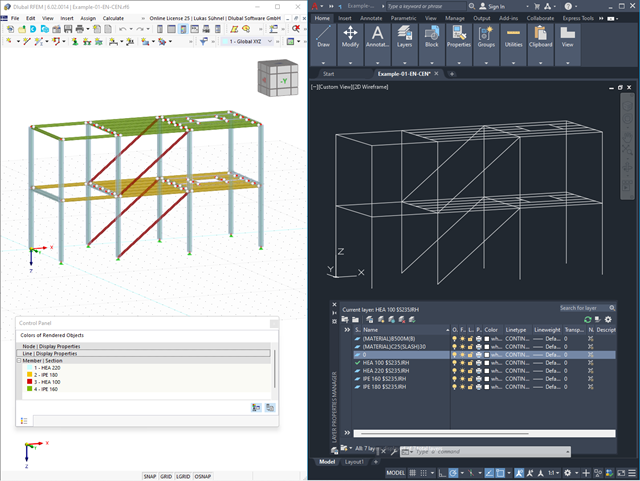
Use the interfaces for more efficient work. You can import your structures in the DXF format as lines from Autodesk AutoCAD into RFEM 6 / RSTAB 9.
Furthermore, you can export different objects (for example, cross-sections) from RFEM 6 / RSTAB 9 to separate layers in Autodesk AutoCAD.

The object types listed below can be graphically assigned to the elements of the structure modeled in the program.
- Nodal supports
- Member shear panels
- Local reductions of member cross-sections
- Member transverse stiffeners
- Member longitudinal welds
- Effective lengths
- Boundary conditions
- Line supports
- Loads
- Member support
- Punching reinforcements
- Mesh refinements
- Surface reinforcements
- Surface results adjustments
- Surface support
- Service classes
- Imperfections

Did you know? You can easily define structural modifications in load cases of the Modal Analysis type. This allows you, for example, to individually adjust the stiffnesses of materials, cross-sections, members, surfaces, hinges, and supports. You can also modify stiffnesses for some design add-ons. Once you select the objects, their stiffness properties are adapted to the object type. In this way, you can define them in separate tabs.
Do you want to analyze the failure of an object (for example, a column) in the modal analysis? This is also possible without any problems. Simply switch to the Structure Modification window and deactivate the relevant objects.

- A wide range of cross-sections, such as rectangular sections, square sections, T‑sections, circular sections, built-up cross-sections, irregular parametric cross-sections, and many others (suitability for design depends on the selected standard)
- Design of cross-laminated timber (CLT)
- Design of timber-based materials and laminated veneer lumber according to EC 5
- Design of tapered and curved members (design method according to the standard)
- Adjustment of the essential design factors and standard parameters is possible
- Flexibility due to detailed setting options for basis and extent of calculations
- Fast and clear results output for an immediate overview of the result distribution after the design
- Detailed output of the design results and essential formulas (comprehensible and verifiable result path)
- Numerical results clearly arranged in tables and graphical display of the results in the model
- Integration of the output into the RFEM/RSTAB printout report

- Manual specification of critical component temperature or automatic determination of component temperature for desired duration
- A wide range of fire curves: standard temperature-time curve, external fire curve, hydrocarbon curve
- Manual adjustment of the essential coefficients for the determination of the steel temperature
- Consideration of hot-dip galvanizing of structural components for the determination of the steel temperature
- Results of a temperature-time diagram for the gas and steel temperature
- Fire protection cladding as a contour or a box cladding with temperature-independent materials can be considered when determining the temperature
- Design of members made of carbon steel or stainless steel
- Cross-section design checks and stability analyses (equivalent member method) according to EN 1993‑1‑2, Clause 4.2.3
- Design checks of the cross-sections of Class 4 according to EN 1993‑1‑2, Annex E.

The design checks for the members you have selected are carried out taking into account the governing component temperature. You can perform the cross-section design checks and stability analyses according to EN 1993‑1‑2, Section 4.2.3, in the Steel Design add-on. All reduction factors and coefficients that are necessary are stored accordingly and are taken into account when determining the load-bearing capacity.
The effective lengths for the equivalent member design are taken directly from the strength entries. You don't need to enter them again.
In each design, perform the cross-section classification first. For the cross-sections of Class 4, the design is performed automatically according to EN 1993‑1‑2, Annex E.

The Steel Design add-on helps you, among other things, to design general cross-sections that are not predefined in the cross-section library. To do this, create a cross-section in the RSECTION program and then import it into RFEM/RSTAB. Depending on the design standard that you have used, you can select from various design formats. One of them is, for example, the equivalent stress analysis. Do you have a license for RSECTION and Effective Cross-Sections? Then you can also perform the design checks that take into account the effective cross-section properties according to EN 1993‑1‑5.